Great 3 Wire Alternator Wiring Diagram
3 Wire Alternator Wiring Diagram
In this post we’ll show everything you need to know about a 3 Wire Alternator Wiring Diagram. An alternator is the most integral component of a car’s engine, despite not requiring much maintenance. It generates electricity, supplies energy, and recharges batteries. The Alternator works to convert mechanical energy. It transforms mechanical energy from converting AC or alternating current to DC or direct current and generates electrical energy.

You may learn the essentials of the circuit from a 3 wire alternator wiring diagram by studying the interconnected three electrical connections. Two steps are involved in wiring an automobile’s starter solenoid and Alternator. The first segment focuses on power circuit connections because starters and alternators generate much electricity.
The second section involves the control circuits. Both starters and alternators have independent control circuitry that regulates their output and switches them on and off. When the wiring process is divided into two parts, the work is more understandable, and the outcomes are far more predictable.
We have several alternatives when it comes to updating the electrical systems for our car’s engine. One of these choices is an alternator with one or three wires. Initially, most automobiles came equipped with three-wire alternators as standard.
GM 3 wire alternator diagram

The main function of the Alternator is to work with the battery and conducts electricity to provide power to the electrical components of the car, such as the lights, fans, and windshield wipers. It converts alternating current to direct current, controls the output voltage, and ensures that each unit receives proper voltage and power. This three-wire alternating wiring diagram shows the connections between the different components.
Ford 3 Wire Alternator Diagram

The three main wires in the circuit are the battery positive cable, voltage detecting cable senses, and ignition wire. The car engine is connected to the ignition input wire. While the voltage detecting wire senses the voltage and is attached to the voltage rectifiers, it carries power from the engine to the Alternator. All components will receive regulated voltage if a three-wire alternator is used. These versatile alternators include built-in voltage rectifiers for power sensing. Unlike one-wire alternators, they can produce and rectify electricity in a single circuit.
How to Connect a 3 Wire Alternator Wiring Diagram?
You’ll need to follow these instructions to connect a 3-wire alternator:
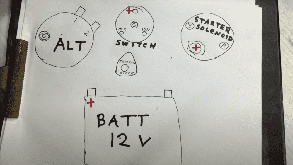
1. Identify the Alternator’s three connection points. The o-ring wire connector rests on a bolt at the bottom connection. Terminals 1 and 2 are placed adjacent to one another on the top and take tiny plugs.
2. The o-ring of the battery-positive cable should be placed on the bolt. Regardless of the type of Alternator, every car needs one as standard.
3. Get a small piece of wire with an O-ring on one end and an appropriate termination plug on the other. After inserting the red wire into terminal 2, cover the bolt with the o-ring side of the wire.
4. To attach the two o-rings to the Alternator, tighten the bolt and nut.
5. The gen, battery, or dashboard light should be connected to terminal 1. Wire a fake light between terminal 1 and turn On the ignition switch.
How to install a 3 Wire Alternator?
How does an Alternator work?
The stator, rotor shafts, and diode bridge rectifier are the three primary parts of the Alternator, along with a voltage regulator. The alternator belt, also known as a V-belt, spins the pulley on the Alternator when the battery first powers the vehicle. Because of that, the rotor spins rapidly inside the Alternator. This rotor, a magnet or collection of magnets, is housed inside the stator, a nest of copper wires.
Electromagnetism is the process by which electricity is produced by spinning magnets at extremely high speeds along a series of copper wires. The electricity obtained in this method travels through copper lines to the alternator’s diode rectifier, where it is converted from AC to DC—the type of current used by the automobile battery, converting mechanical energy to an electrical supply.
The voltage regulator, a built-in element on current alternators, functions as a gatekeeper, cutting off power to the battery if the voltage increases above a set point, typically 14.5 volts, to prevent the battery from being overcharged. The cycle continues as the engine battery is depleted and current is permitted to return to it from the Alternator.
What are the main wires in the Alternator?
The main battery positive wire, the voltage sensing wire, and the ignition input wire are the main wires that make up an alternator are the main battery positive wire, voltage detecting cable senses, and ignition input. These wires supply the Alternator with power and aid in controlling its output. These cables’ intended uses are listed below.
Battery Positive Wire
An alternator’s primary positive wire is connected to the output port on the device’s back. It is the location where the Alternator sends electrical current to the battery.
Voltage Sensing Wire
An alternator’s voltage sensing wire is connected to the voltage regulator’s battery side. It aids the regulator in sensing the voltage and controlling the Alternator’s output.
Ignition Input Wire
An alternator’s field ignition input wire is connected to the ignition warning light. The driver can use it to determine when the Alternator is malfunctioning. By connecting these wires, you can guarantee that the Alternator will run effectively and can power the car’s electrical system. The Alternator could not function or trigger without these wires.
How to wire a 3 Wire Alternator Wiring Diagram?
The mechanical energy produced by the engine’s rotation and the movement of the drive belt is transformed into electrical energy by an alternator. When the engine is running, the Alternator serves as the primary power source for the entire vehicle while also recharging the battery.
As its name suggests, the three-wire Alternator requires three wires to operate. When dealing with a direct replacement, the procedure is very straightforward:
- Remember the wiring connections and where the plugs are located.
- Remove them.
- Reinstall the new Alternator.
Wiring System
An alternator has a complex wiring system since it is connected to many components. The exciter wire, positive and negative wires, and other wiring make up the main wiring system. The exciter wire is connected to the L terminal of an alternator and is used to turn on the voltage regulator. If you old hot rod needs a new wiring system? Consider checking out Painless performance.
Smaller terminals that connect to the battery’s positive terminal and negative terminal are called positive and negative cables. The Alternator also displays a connection to the “battery charging line,” even though it solely serves to charge the battery and not power any other components. The key switch is connected to the Alternator through an ignition input wire. The ignition wire activates the voltage regulator.
Wiring Diagram
The alternator wiring diagrams that are provided below serve a variety of functions. Let’s examine their relationships.
External Electromechanical Voltage Regulator
The voltage sensor cable is twined into an electromagnet in the electromechanical regulators. It produces a magnetic field around the magnet, attracting the ferrous block in its direction. There are three electromagnetic switches in such circuits—cutout relays, a regulator, and a current regulator. The regulator and current regulator switch manage the voltage output by controlling the Alternator’s field circuit, while the cutout relay connects the battery to the generator.
However, due to their ineffective mechanism, electromechanical circuits are seldom used in production vehicles, even though they are crucial for AC stabilizing circuits.
PCM Controlled Wiring Diagram
An advanced sort of Alternator that employs internal modules to control the field circuit of an engine is one with powertrain control module (PCM) voltage regulation circuits. The PCM controls the current flow by analyzing data from the body control module (BCM) and comprehending a system’s charging requirements.
When the voltage falls below the desired level, the modules are activated, which alters the period that current flows through the coil when it is turned on. As a result, the system output is modified to meet its requirements. The PCR-controlled alternators are incredibly effective at producing the required voltages.
What is the Importance of Wiring Diagrams?
Once the engine has been started, an automobile cannot function without an alternator. Alternators require intricate wiring, and the wires must be linked to the proper components and terminals. Designing alternator wiring schematics will make this easier. A wire alternator wiring schematic shows a circuit’s connections and physical arrangement.
Having a clear idea of each component’s wiring connections and placement makes it simpler to construct circuits and connect the Alternator properly. It is essential to design circuits with sufficient wiring so that each piece of equipment receives the correct voltage and is neither overpowered nor underpowered.
Final Thoughts
When the engine is started, alternators help keep the car going. Wires for alternators must be connected to the correct units and terminals, which involves intricate wiring. Be sure to use the correct wire gauge during the install. If you are having trouble with your alternator? Be sure to check out post how to test your alternator without a multimeter.
The circuit’s physical connections and overall design are shown graphically in wiring diagrams. Making circuits and properly connecting the Alternator is easier with a clear visual of each component’s wiring connections and placement. Circuits with suitable wiring must be created to ensure that no equipment receives an excessive or inadequate voltage.
Leave a Reply